<TODO: Recover page>
Tag: MissingImages
Iron Man 3 Chest Arc Reactor
I made this prop to wear to the Iron Man 3 release (and to test out some new technology for a future project).
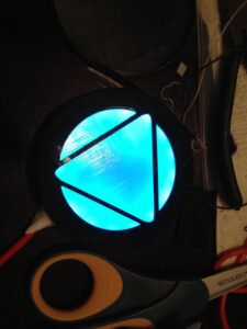
The whole thing was designed in OpenSCAD and 3D printed in ABS (both the housing and the diffusor puck). A Teensy 2 module drives the LED strip (WS2812 clone, 60 pixels/m) and is is wired up to a BLE112 module for communications.
You can control it via Bluetooth (no app yet, you hand craft a 1, 3, 6, or 7 byte message in a BLE explorer app to set a greyscale color, or one/two RGB colors and a ping-pong speed). By default it boots up into ‘Arc reactor blue’ with a soft breathing animation.


Exploding Slime Painter
This past weekend was the 2012 Triangle Game Jam. Our theme was game titles generated by madlibs: everyone contributed a list of 5 adjectives, 5 nouns, and 5 verb stems, and a program generated random game names from them. From there, we pitched ideas based on the titles and formed teams.
There were a lot of good titles, but the one I pitched and ended up making into a game is Exploding Slime Painter. The team consisted of Mike Daly, Michael Noland, and Frank Voelker, with some sounds from Ash Gowland.
Downloads
- Exploding Slime Painter
- XNA 4 redistributable package (needed to play the game)
- Source code and artwork
How to Play
It’s a score-attack game for one or two players trying to paint objectives in their team color, but take time to watch in delight as slimes wobble around and explode.
- Explode slimes to earn points and unleash their colorful painting goo
- Paint and hold objectives in your color for a big ongoing score
- Kicked slimes will explode on impact, giving you bonus points
Controls
Best played with an Xbox 360 controller, but can be played on the keyboard as well.
Player 1 (Red):
- Use the arrow keys or the left thubmstick to move around
- Press [RightCtrl] or gamepad [A] to kick slimes in front of you
- Hold the kick button down to charge the kick, sending them father
- Hold [RightShift] or gamepad [B] to summon red slimes to your side
Player 2 (Blue):
- Use the arrow keys or the left thubmstick to move around
- Press [Space] or gamepad [A] to kick slimes in front of you
- Hold the kick button down to charge the kick, sending them father
- Hold [LeftShift] or gamepad [B] to summon blue slimes to your side
Notes
- Additional content was used under license from artisticdude, Daniel Cook, Charles Gabriel, and Kevin MacLeod (for more information, see the LICENSE.txt file).
- The game should be called ‘Explosive Slime Painter’ under the madlib construction rules, but we ran with the title right out of the madlib generator as it didn’t make a difference: the slimes are explosive and they end up exploding.
Planes on a Snake
This past weekend was the 4th annual Global Game Jam, and we hosted a site in the triangle again. I was an organizer this year, but I still had plenty of time to jam, creating Planes on a Snake with my team. The theme was a picture of an ouroboros, which we interpreted by setting a shmup on the back of the world serpent.
Brief Play Description
A rift in spacetime has resulted in a large number of World War II era planes getting stuck on the world snake.
Join the frequent fliers club of Ouroboros Airlines, racking up points while taking advantage of the torus nature of your new environment.
(video contains some strong language)
You have three weapons at your disposal:
- Single shot – the default weapon
- Spread shot – Three times the fun
- The Lazër – A beam weapon that goes to 11
You progress thru the weapons as you collect powerups dropped by fallen enemies.
Once the meter is at least half full, you can activate the lazër, which fires until your reserves are depleted.
Scoring
- Bullets will fly around and around forever, so watch out for crossfire from your own shots.
- Earn more points by hitting adversaries with shots that have been flying for a long time.
- Death is transient on the world snake, both you and your adversaries will eventually respawn.
- Make as many points as you can during the time limit to earn your place in the frequent fliers club.
Jammers
- Stephen Hodgson
- Scott Jacobs
- Luv Kohli
- Michael Noland
- Chris VanderKnyff
Additional graphics by
- David Gervais
Original GGJ page.
Download
Download the game or source code.
Screenshots:


Speeding up LPD8806 show() without hardware SPI
If you’re using LPD8806 LED strips and you can’t use the hardware SPI port (e.g., when using an Ethernet board), there are two other options in the Adafruit library: the default mode and ‘slowmo’ mode. The default mode is decent, but the flexibility of being able to choose the pins at runtime comes with a cost.
However, you can still get a decent speedup by defining your pin usage at compile time in a replacement show() function. I measured the time required to update an 86 LED strip using each method on an EtherTen board (Atmega328 @ 16 MHz, same as the Uno):
30.23 ms - Adafruit 'slowmo' method (digitalWrite)
7.76 ms - Adafruit default method (port pointers)
1.54 ms - Compile-time method
1.43 ms - Adafruit hardware SPI method
The timing was done using micros() around the show() call with strip.pause = 0.
I’ve tried to make this method as minimally hardcoded as possible. To use, throw the code from CompileTimeLEDs.h into the LPD8806 class in LPD8806.h and replace:
int ClockPin = 3;
int DataPin = 2;
...
strip.show();
with:
const int ClockPin = 3;
const int DataPin = 2;
...
strip.showCompileTime<ClockPin, DataPin>();
This overload is only available on ATmega168 or ATmega328 boards; on the Arduino Mega or other random boards, you need to specify the port register and use pin offsets within the port instead of the Arduino board pin number (e.g., showCompileTime<0..7, 0..7>(PORTD, PORTD))
CompileTimeLEDs.h (Download)
template<unsigned int ClockPin>
void PulseClockLine(volatile uint8_t& ClockRegister)
{
  const byte LED_CLOCK_MASK = 1 << ClockPin;
  ClockRegister |= LED_CLOCK_MASK;
  ClockRegister &= ~LED_CLOCK_MASK;
}

template<unsigned int ClockPin, unsigned int DataPin>
void TransmitBit(byte& CurrentByte, volatile uint8_t& ClockRegister, volatile uint8_t& DataRegister)
{
  // Set the data bit
  const byte LED_DATA_MASK = 1 << DataPin;
  if (CurrentByte & 0x80)
  {
    DataRegister |= LED_DATA_MASK;
  }
  else
  {
    DataRegister &= ~LED_DATA_MASK;
  }

  // Pulse the clock line
  PulseClockLine<ClockPin>(ClockRegister);

  // Advance to the next bit to transmit
  CurrentByte = CurrentByte << 1;
}

#if defined(__AVR_ATmega328P__) || defined(__AVR_ATmega168__)
  #define MAP_ARDUINO_PIN_TO_PORT_PIN(ArduinoPin) \
    ( ArduinoPin & 7 )

  #define MAP_ARDUINO_PIN_TO_PORT_REG(ArduinoPin) \
    ( (ArduinoPin >= 16) ? PORTC : (((ArduinoPin) >= 8) ? PORTB : PORTD) )

  // Specify Arduino pin numbers
  template<unsigned int ClockPin, unsigned int DataPin>
  void showCompileTime()
  {
    showCompileTime<MAP_ARDUINO_PIN_TO_PORT_PIN(ClockPin), MAP_ARDUINO_PIN_TO_PORT_PIN(DataPin)>(
      MAP_ARDUINO_PIN_TO_PORT_REG(ClockPin),
      MAP_ARDUINO_PIN_TO_PORT_REG(DataPin));
  }

  #undef MAP_ARDUINO_PIN_TO_PORT_PIN
  #undef MAP_ARDUINO_PIN_TO_PORT_REG
#else
  // Sorry: Didn't write an equivalent for other boards; use the other
  // overload and explicitly specify ports and offsets within those ports
#endif

// Note: Pin template params need to be relative to their port (0..7), not Arduino pinout numbers
template<unsigned int ClockPin, unsigned int DataPin>
void showCompileTime(volatile uint8_t& ClockRegister, volatile uint8_t& DataRegister)
{
  // Clock out the color for each LED
  byte* DataPtr = pixels;
  byte* EndDataPtr = pixels + (numLEDs * 3);

  do
  {
    byte CurrentByte = *DataPtr++;

    TransmitBit<ClockPin, DataPin>(CurrentByte, ClockRegister, DataRegister);
    TransmitBit<ClockPin, DataPin>(CurrentByte, ClockRegister, DataRegister);
    TransmitBit<ClockPin, DataPin>(CurrentByte, ClockRegister, DataRegister);
    TransmitBit<ClockPin, DataPin>(CurrentByte, ClockRegister, DataRegister);

    TransmitBit<ClockPin, DataPin>(CurrentByte, ClockRegister, DataRegister);
    TransmitBit<ClockPin, DataPin>(CurrentByte, ClockRegister, DataRegister);
    TransmitBit<ClockPin, DataPin>(CurrentByte, ClockRegister, DataRegister);
    TransmitBit<ClockPin, DataPin>(CurrentByte, ClockRegister, DataRegister);
  }
  while (DataPtr != EndDataPtr);

  // Clear the data line while we clock out the latching pattern
  const byte LED_DATA_MASK = 1 << DataPin;
  DataRegister &= ~LED_DATA_MASK;

  // All of the original data had the high bit set in each byte.  To latch
  // the color in, we need to clock out another LED worth of 0's for every
  // 64 LEDs in the strip apparently.
  byte RemainingLatchBytes = ((numLEDs + 63) / 64) * 3;
  do
  {
    PulseClockLine<ClockPin>(ClockRegister);
    PulseClockLine<ClockPin>(ClockRegister);
    PulseClockLine<ClockPin>(ClockRegister);
    PulseClockLine<ClockPin>(ClockRegister);

    PulseClockLine<ClockPin>(ClockRegister);
    PulseClockLine<ClockPin>(ClockRegister);
    PulseClockLine<ClockPin>(ClockRegister);
    PulseClockLine<ClockPin>(ClockRegister);
  } while (--RemainingLatchBytes);

  // Need a bit of a delay before clocking again, but ideally this
  // is set to 0 and meaningful work is done instead
  if (pause)
  {
    delay(pause);
  }
}
License: CC0 (Placed into the public domain).
The avr-gcc compiler seems to do fine at recognizing the compile time constants and doing the right thing in codegen, as this method is just as fast as my original macrotastic implementation. You can probably eke out some more performance (would be nice to beat the hardware SPI implementation ^_^), but this was enough to get the headroom I needed.
Christmas gifts: Candles
One of the things I made for Christmas gifts this year were candles. In addition to the typical cylinder and square candles, I made some candles in the form of the Gears omen and a lime.
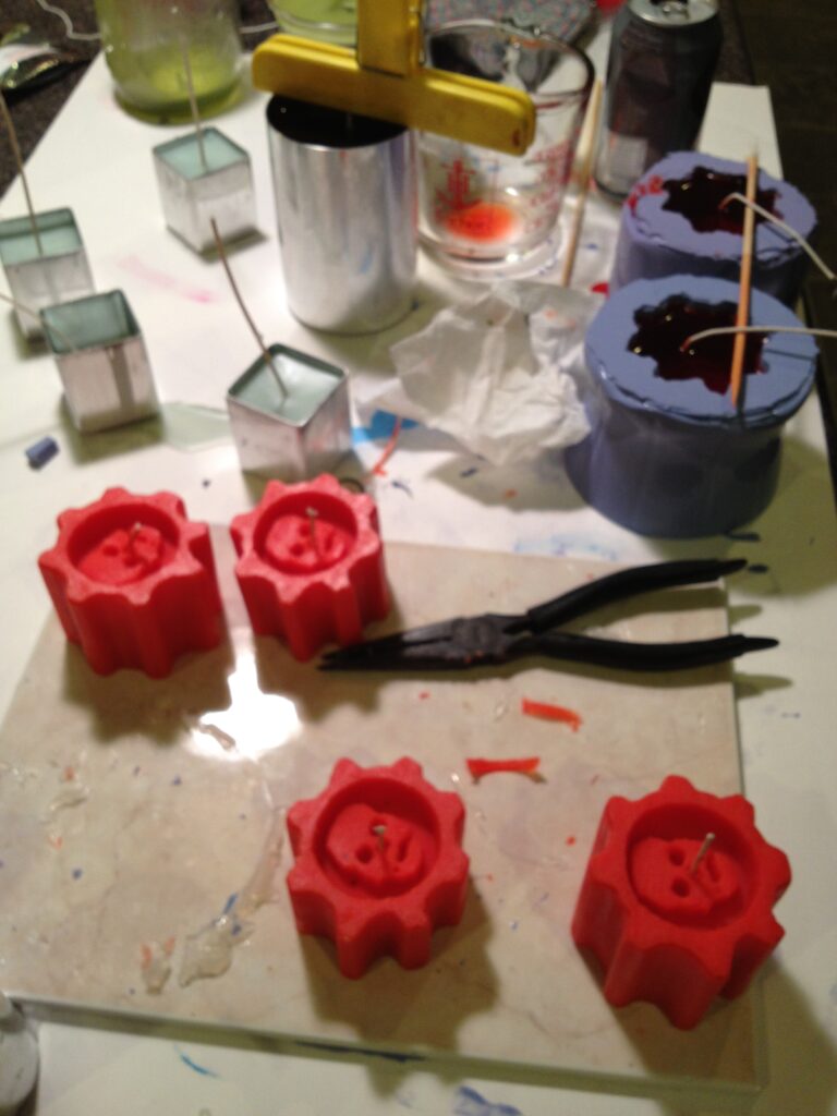
For my first time making molds, and first time pouring candles, I’m really happy with how things came out.
I cast the first few batches using votive wax, which only takes one pour and gives a creamy consistency, but they lose their shape pretty fast when lit. After that, I switched to a pillar wax, which has a little more surface mottling and needs 2+ pours, but keeps it’s structure much better. Most of the candle supplies came from a site called CandleScience, which is actually in the area, so I can order online and pick up the order the next day without having to pay shipping.
I’d done a bit of reading about mold making in the past, but there was a class on molds and resin casting at The Gamer’s Armory that convinced me to order some supplies from Smooth-On. I used OOMOO 30 for both molds. The lime mold was made using a real lime skewered with a wooden stick, while the omen candles were made from a wooden positive modeled in VCarve Pro and cut on my CNC. It was made of 3 layers of 0.75 in plywood glued together and sprayed with some clearcoat. I cast two molds using sections of 2L soda bottles hot glued* to a floor tile.


*A word to the wise: High-temp hot glue is hot enough to melt PET soda bottles! One of the two molds wasn’t sealed properly as a result and I had a decent sized leak of the purple ooze, but thankfully I had everything centered on a large piece of foamcore, so it didn’t ruin my countertop. Next time I’ll probably use clay as a seal.
Glitchovision 3000
This is an audiovisual instrument that I created for the 555 timer contest.
The Glitchovision 3000 is a 4 step sequencer controlling an ‘Atari Punk‘ synth with a greyscale NTSC video visualization of the output audio, built using two 558 quad-timers and two 556 dual-timers.
Here is a video of it in action:
Theory of operation
- Video timing (two parallel channels of 1/2 556 feeding into 2/4 558, and finally combined via some 74ls08 AND gates).
- Audio generation (4 step sequencer built from a 558 feeding into a 556 setup as a stepped tone generator).
Video timing (556 feeding into a 558)
First, a 556 (configured as two astable timers) generates two independent blanking signals, one horizontal and one vertical.
These signals are low for the time specified in the RS170 standard (3 lines for vsync, 10.9 us for hsync), although the final result isn’t exactly up to RS170 spec. It generates a ‘combined’ or industrial sync (which works on every TV I’ve ever tested), but RS170 requires serrating and equalizing pulses to be generated during vsync to prevent 1950s hsync oscillators from losing tracking.
Each blanking signal is fed into a 558 monostable timer, which generates the blanking signal (lasting longer than the sync signal and delaying until the image is about past the overscan).
The output of the h or v blank is fed into a second pair of 558 timers to generate an ‘active’ region of the screen, where we can display arbitrary data.
The two sync signals are combined with one AND gate into a CSYNC signal and the two active signals are combined (with wired AND from the 558 open-collector outputs, but buffered into another AND gate) to generate a CACTIVE signal.
These signals are used to generate the final composite video output, when combined with the audio signal.

Audio (558 feeding into a 556)
One 558 quad timer serves as a 4 step sequencer, similar to a traditional use of a 4017 decade counter. All four steps use the same timing components, but the overall step rate is controlled by varying the control voltage for the 558 timer. You can chain several 558’s together to get longer sequence lengths, but I only ended up wiring switches and pots for 4 steps.
The output of the sequencer is combined with the ‘left’ potentiometer of an atari punk synth implemented in the other 556 (conflating the two for the timing of the astable portion of the synth). The monostable portion of the Atari punk is bog standard, triggered by the astable portion.
The audio output is line conditioned and output, as well as being ANDed with the CACTIVE signal and merged with CACTIVE via some mixing pots to generate a final video signal. Listen and see that atonal goodness.

Notes:
- Note 1: Adding a reset switch instead of relying on power-sequencing during startup seems like a solid addition. I didn’t have it in the prototype shown in the video, so it’s listed in the schematic in a dashed box. It would also provide a nice ‘tap to the rhythm’ reset, although it wouldn’t stop the later stages from playing like a reset on a 4017 would.
- Note 2,3: Adding a pair of diodes here to keep the range of CV to ~0.7 to 4.3 V, or even some fixed value resistors should help prevent nastyness when the control voltage is taken too far out of whack.
- Note 4: The other 558 in the lid board isn’t used. It’s partially wired up, but it’s not tied into the countdown of the main 558 sequencer, as I didn’t have time to wire up the other 4 switches and pots.
- Note 5: Using the opposite end of the sequencer potentiometers as part of the timing circuit for another 558 counting verticallly downwards after triggering on vblank (and wired-ANDing the outputs from them with the output of the sequencer 558) should provide a visual indication of what the notes are (will need to move the switches to after the potentiometers).


The timings were worked out in an Excel spreadsheet (note: you might need to rename it back to xlsx to open it if it downloads as a ZIP).
The original writeup for the compo is still available at http://auia.net/timercompo/video555entry.html.
Persistence of vision display using only 555 timers
I created this display for the 555 timer contest, a compact art piece that cries out in appreciation of the venerable 555 timer. It’s a persistence of vision display formed by 7 blue leds and 3 NE555 timers, which spells out 5 5 5 as it revolves.

Theory of Operation
- The first 555 is setup as an astable oscillator, with the reset triggered by the tachometer output of the PC fan that the whole thing is mounted on. This timer generates the ‘horizontal’ parts of the 5.
- The second 555 is positive edge triggered (using a transistor NOT and a capacitor to generate the level input the 555 wants), and generates the *right* edge of the 5 (kind of counter-intuitive, but it spins counterclockwise).
- The third 555 is negative edge triggered (capacitor filter) and generates the left edge of the 5.
- Three 5’s are created by tuning the first astable 555’s period to complete 3 cycles in 1/4 of a revolution (the tachometer is high for 1/4 rev, low for 1/4, high for 1/4, low for 1/4, so you get two copies per full revolution).


The original writeup for the compo is still available at http://auia.net/timercompo/pov555entry.html.
Hubert’s Safari Adventure
A game for one player using an Xbox controller or mouse and keyboard, wherein you exterminate dodos for a tyrannosaur named Hubert.
- Hubert runs a park with the allegedly extinct dodo.
- You have gotten a pass to go hunting on his lands.
- Kill as many dodos as you can in the time limit.
- Use ice cream to attract the dodos, and then crush them!
- Drive them before you! Hear the lamentations of the hens!
- Bonus time and money is awarded for high-efficiency extinction.
- The game ends when time expires.

This is the game I worked on at the 3rd Global Game Jam, where the theme was Extinction. You can see more screenshots and download the game at the global game jam page.
Team:
- Alexander C. Park
- Autumn Ford
- Chris VanderKnyff
- Harrison Moore
- Michael Kelley
- Michael Noland
- Nick Darnell
Stylized level
Playing around a little bit with a stylized rendering idea for a 2D platformer that popped into my head (looks better in motion).
