I took 3rd place in the minimalist category of the 555 timer compo for my persistence of vision display. I’d also like to thank Allerta and CafeLogic for sponsoring the compo and the cool prizes (an iPulse watch and a box o displays).
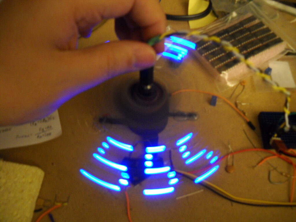
I took 3rd place in the minimalist category of the 555 timer compo for my persistence of vision display. I’d also like to thank Allerta and CafeLogic for sponsoring the compo and the cool prizes (an iPulse watch and a box o displays).
This is an audiovisual instrument that I created for the 555 timer contest.
The Glitchovision 3000 is a 4 step sequencer controlling an ‘Atari Punk‘ synth with a greyscale NTSC video visualization of the output audio, built using two 558 quad-timers and two 556 dual-timers.
Here is a video of it in action:
First, a 556 (configured as two astable timers) generates two independent blanking signals, one horizontal and one vertical.
These signals are low for the time specified in the RS170 standard (3 lines for vsync, 10.9 us for hsync), although the final result isn’t exactly up to RS170 spec. It generates a ‘combined’ or industrial sync (which works on every TV I’ve ever tested), but RS170 requires serrating and equalizing pulses to be generated during vsync to prevent 1950s hsync oscillators from losing tracking.
Each blanking signal is fed into a 558 monostable timer, which generates the blanking signal (lasting longer than the sync signal and delaying until the image is about past the overscan).
The output of the h or v blank is fed into a second pair of 558 timers to generate an ‘active’ region of the screen, where we can display arbitrary data.
The two sync signals are combined with one AND gate into a CSYNC signal and the two active signals are combined (with wired AND from the 558 open-collector outputs, but buffered into another AND gate) to generate a CACTIVE signal.
These signals are used to generate the final composite video output, when combined with the audio signal.

One 558 quad timer serves as a 4 step sequencer, similar to a traditional use of a 4017 decade counter. All four steps use the same timing components, but the overall step rate is controlled by varying the control voltage for the 558 timer. You can chain several 558’s together to get longer sequence lengths, but I only ended up wiring switches and pots for 4 steps.
The output of the sequencer is combined with the ‘left’ potentiometer of an atari punk synth implemented in the other 556 (conflating the two for the timing of the astable portion of the synth). The monostable portion of the Atari punk is bog standard, triggered by the astable portion.
The audio output is line conditioned and output, as well as being ANDed with the CACTIVE signal and merged with CACTIVE via some mixing pots to generate a final video signal. Listen and see that atonal goodness.

Notes:


The timings were worked out in an Excel spreadsheet (note: you might need to rename it back to xlsx to open it if it downloads as a ZIP).
The original writeup for the compo is still available at http://auia.net/timercompo/video555entry.html.
I created this display for the 555 timer contest, a compact art piece that cries out in appreciation of the venerable 555 timer. It’s a persistence of vision display formed by 7 blue leds and 3 NE555 timers, which spells out 5 5 5 as it revolves.

Theory of Operation


The original writeup for the compo is still available at http://auia.net/timercompo/pov555entry.html.