Iron Man 3 Chest Arc Reactor

I made this prop to wear to the Iron Man 3 release (and to test out some new technology for a future project).

Arc Reactor

The whole thing was designed in OpenSCAD and 3D printed in ABS (both the housing and the diffusor puck).  A Teensy 2 module drives the LED strip (WS2812 clone, 60 pixels/m) and is is wired up to a BLE112 module for communications.

You can control it via Bluetooth (no app yet, you hand craft a 1, 3, 6, or 7 byte message in a BLE explorer app to set a greyscale color, or one/two RGB colors and a ping-pong speed).  By default it boots up into ‘Arc reactor blue’ with a soft breathing animation.

Prototype case design
Diffusor Test
Innards
Fully assembled
Glowy Victory
Thru T-Shirt
Iron Man Selfie

Speeding up LPD8806 show() without hardware SPI

If you’re using LPD8806 LED strips and you can’t use the hardware SPI port (e.g., when using an Ethernet board), there are two other options in the Adafruit library: the default mode and ‘slowmo’ mode. The default mode is decent, but the flexibility of being able to choose the pins at runtime comes with a cost.

However, you can still get a decent speedup by defining your pin usage at compile time in a replacement show() function. I measured the time required to update an 86 LED strip using each method on an EtherTen board (Atmega328 @ 16 MHz, same as the Uno):

30.23 ms - Adafruit 'slowmo' method (digitalWrite)
7.76 ms - Adafruit default method (port pointers)
1.54 ms - Compile-time method
1.43 ms - Adafruit hardware SPI method

The timing was done using micros() around the show() call with strip.pause = 0.

I’ve tried to make this method as minimally hardcoded as possible. To use, throw the code from CompileTimeLEDs.h into the LPD8806 class in LPD8806.h and replace:

int ClockPin = 3;
int DataPin = 2;
...
strip.show();

with:

const int ClockPin = 3;
const int DataPin = 2;
...
strip.showCompileTime<ClockPin, DataPin>();

This overload is only available on ATmega168 or ATmega328 boards; on the Arduino Mega or other random boards, you need to specify the port register and use pin offsets within the port instead of the Arduino board pin number (e.g., showCompileTime<0..7, 0..7>(PORTD, PORTD))

CompileTimeLEDs.h (Download)

template<unsigned int ClockPin>
void PulseClockLine(volatile uint8_t& ClockRegister)
{
  const byte LED_CLOCK_MASK = 1 << ClockPin;
  ClockRegister |= LED_CLOCK_MASK;
  ClockRegister &= ~LED_CLOCK_MASK;
}
 
template<unsigned int ClockPin, unsigned int DataPin>
void TransmitBit(byte& CurrentByte, volatile uint8_t& ClockRegister, volatile uint8_t& DataRegister)
{
  // Set the data bit
  const byte LED_DATA_MASK = 1 << DataPin;
  if (CurrentByte & 0x80)
  {
    DataRegister |= LED_DATA_MASK;
  }
  else
  {
    DataRegister &= ~LED_DATA_MASK;
  }
 
  // Pulse the clock line
  PulseClockLine<ClockPin>(ClockRegister);
 
  // Advance to the next bit to transmit
  CurrentByte = CurrentByte << 1;
}
 
#if defined(__AVR_ATmega328P__) || defined(__AVR_ATmega168__)
  #define MAP_ARDUINO_PIN_TO_PORT_PIN(ArduinoPin) \
    ( ArduinoPin & 7 )
 
  #define MAP_ARDUINO_PIN_TO_PORT_REG(ArduinoPin) \
    ( (ArduinoPin >= 16) ? PORTC : (((ArduinoPin) >= 8) ? PORTB : PORTD) )
 
  // Specify Arduino pin numbers
  template<unsigned int ClockPin, unsigned int DataPin>
  void showCompileTime()
  {
    showCompileTime<MAP_ARDUINO_PIN_TO_PORT_PIN(ClockPin), MAP_ARDUINO_PIN_TO_PORT_PIN(DataPin)>(
      MAP_ARDUINO_PIN_TO_PORT_REG(ClockPin),
      MAP_ARDUINO_PIN_TO_PORT_REG(DataPin));
  }
 
  #undef MAP_ARDUINO_PIN_TO_PORT_PIN
  #undef MAP_ARDUINO_PIN_TO_PORT_REG
#else
  // Sorry: Didn't write an equivalent for other boards; use the other
  // overload and explicitly specify ports and offsets within those ports
#endif
 
// Note: Pin template params need to be relative to their port (0..7), not Arduino pinout numbers
template<unsigned int ClockPin, unsigned int DataPin>
void showCompileTime(volatile uint8_t& ClockRegister, volatile uint8_t& DataRegister)
{
  // Clock out the color for each LED
  byte* DataPtr = pixels;
  byte* EndDataPtr = pixels + (numLEDs * 3);
 
  do
  {
    byte CurrentByte = *DataPtr++;
 
    TransmitBit<ClockPin, DataPin>(CurrentByte, ClockRegister, DataRegister);
    TransmitBit<ClockPin, DataPin>(CurrentByte, ClockRegister, DataRegister);
    TransmitBit<ClockPin, DataPin>(CurrentByte, ClockRegister, DataRegister);
    TransmitBit<ClockPin, DataPin>(CurrentByte, ClockRegister, DataRegister);
 
    TransmitBit<ClockPin, DataPin>(CurrentByte, ClockRegister, DataRegister);
    TransmitBit<ClockPin, DataPin>(CurrentByte, ClockRegister, DataRegister);
    TransmitBit<ClockPin, DataPin>(CurrentByte, ClockRegister, DataRegister);
    TransmitBit<ClockPin, DataPin>(CurrentByte, ClockRegister, DataRegister);
  }
  while (DataPtr != EndDataPtr);
 
  // Clear the data line while we clock out the latching pattern
  const byte LED_DATA_MASK = 1 << DataPin;
  DataRegister &= ~LED_DATA_MASK;
 
  // All of the original data had the high bit set in each byte.  To latch
  // the color in, we need to clock out another LED worth of 0's for every
  // 64 LEDs in the strip apparently.
  byte RemainingLatchBytes = ((numLEDs + 63) / 64) * 3;
  do 
  {
    PulseClockLine<ClockPin>(ClockRegister);
    PulseClockLine<ClockPin>(ClockRegister);
    PulseClockLine<ClockPin>(ClockRegister);
    PulseClockLine<ClockPin>(ClockRegister);
 
    PulseClockLine<ClockPin>(ClockRegister);
    PulseClockLine<ClockPin>(ClockRegister);
    PulseClockLine<ClockPin>(ClockRegister);
    PulseClockLine<ClockPin>(ClockRegister);
  } while (--RemainingLatchBytes);
 
  // Need a bit of a delay before clocking again, but ideally this
  // is set to 0 and meaningful work is done instead
  if (pause)
  {
    delay(pause);
  }
}

License: CC0 (Placed into the public domain).

The avr-gcc compiler seems to do fine at recognizing the compile time constants and doing the right thing in codegen, as this method is just as fast as my original macrotastic implementation. You can probably eke out some more performance (would be nice to beat the hardware SPI implementation ^_^), but this was enough to get the headroom I needed.
Reducing code size on Arduino Ethernet boards

The Ethernet library grew in size several KB from 0022 to 1.0, which is a big deal when you only have 32 KB to play with. You can save about 2 KB by compiling out DNS support:

Wrap the following pieces of code in #if WITH_DNS

  • Dns.cpp and Dns.h:
    The entire file
  • EthernetClient.h and EthernetClient.cpp:
    int connect(const char* host, uint16_t port)
  • EthernetUDP.h and EthernetUDP.cpp:
    int beginPacket(const char *host, uint16_t port)
  • Client.h:
    virtual int connect(const char *host, uint16_t port)
  • Udp.h:
    virtual int beginPacket(const char *host, uint16_t port)

Add #include "EthernetUDP.h" to EthernetUDP.cpp, since it’s currently relying on the indirect include from Dns.h.

Faster Arduino development

I’ve been using Arduino boards for a bunch of random projects lately. They may not be as inexpensive or as small as throwing together a microcontroller and a resonator on a piece of perf board, but they’re a lot faster when making one-offs: lots of shields with ready-to-go libraries, quick programming / test cycle, etc…

One major downside is that the official Arduino IDE has a super-awful text editor, but there is a solution. Visual Micro has a plugin called Arduino for Visual Studio that makes everything ‘just work’ in the VS IDE, even VAX. Install the Arduino 1.0 IDE, then install the plugin, and all you have to do is point the plugin to your Arduino directory the next time you run devenv. It handles the rest, setting up syntax highlighting for .ino/.pde files, adds a toolbar to pick the board type and COM port, etc… To top it all off, it compiles about 10 times faster than the official IDE (0.2 – 0.5 s versus 5-10s); so much faster that it seems like there is a bug in the current version of the Arduino IDE.

Long story short, if you are doing any Arduino development and have VS 2008 or VS 2010 (the express edition won’t work since it doesn’t have support for plugins), you should download it now for a massive productivity boost.

Robotender Mk3

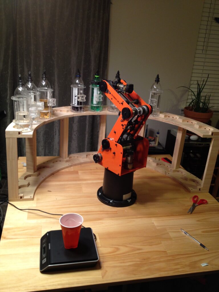
Finished Robotender Mk3 just in time for my halloween party (with literally minutes to spare). This one is a pretty radical departure from the previous designs, using a robotic arm instead of pressurized dispensing. I managed to pick up a Scorbot ER-III arm and controller off of eBay. They were originally used for teaching robotics and motion planning at universities, and are generally pretty used-and-abused (two motors were almost falling out of their mounts on this one), but it runs quite nicely after everything was cleaned and tightened up.

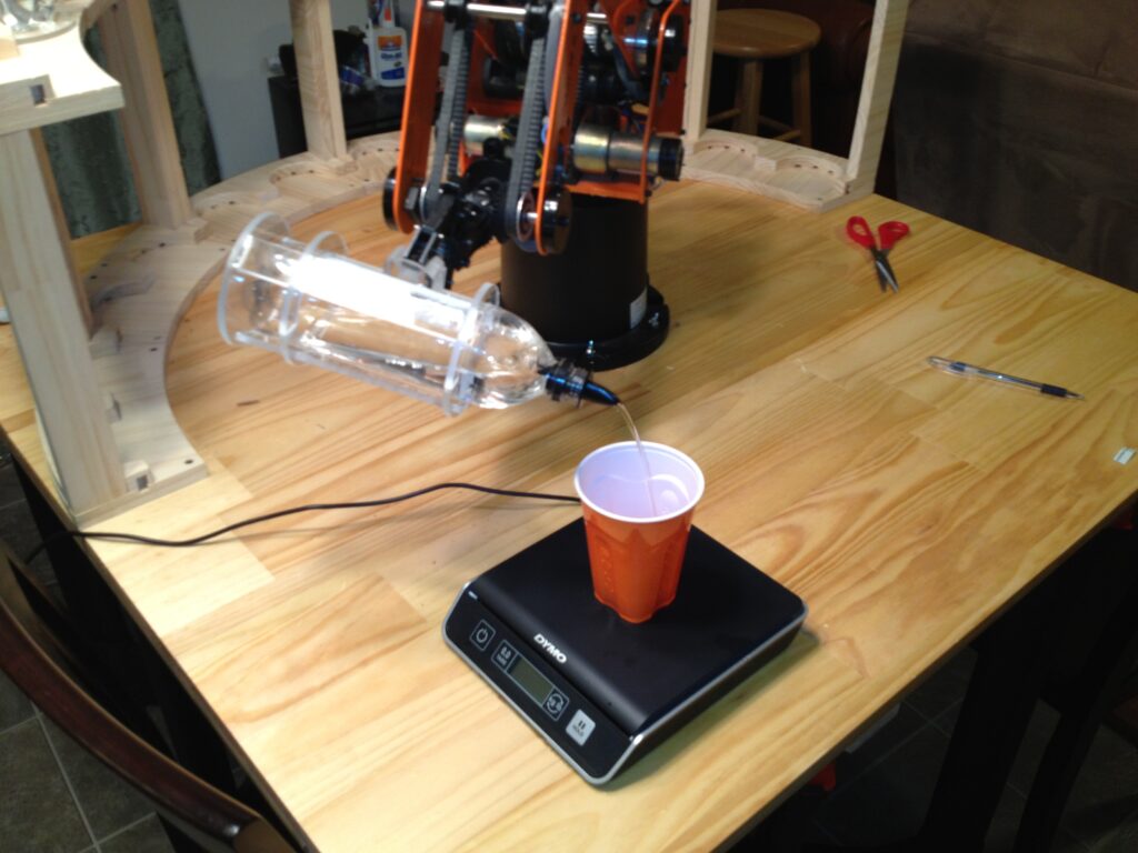
It’s a little slow compared to the Mk1, but it’s a lot of fun to watch, can hold more bottles, and is easier to maintain. It uses custom bottle carriers that hold 710 mL soda bottles, and can hold up to 24 such bottles. There is a digital scale hooked up to the computer as well, which gets zeroed once a bottle reaches the pour site, letting it determine how much liquid has been poured much more accurately than the simple time-based approach used in Mk1.

Pouring an ingredient

I took a number of pictures during construction on this one, so I may do a build log post later.

Next steps:

  • I’m going to look into building a new motor controller for it, so I can get better feedback and drive it faster while still keeping a solid grip on bottles (can’t currently ignore the gripper stall state for fear of missing any other motor stalls, meaning I have to do a slow 1/10th speed backout on the gripper to get the max grab force I can).
  • The bottle holders are on their 6th iteration already, but positive grip is still a bit of a problem, so I’m probably going to redesign the bottle holders with a triangular slot and make some triangular nylon plates for the gripper. This might also allow me to be a little less precise in the back-off, and speed it up without a new motor controller.

Infected Omen Light Box

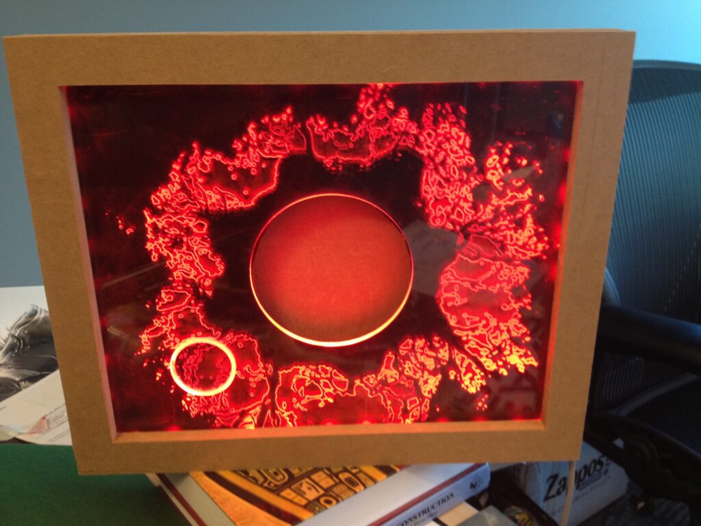
I pulled an all-nighter and designed/fabricated a LED edge lighting box plus etched plate in advance of the Gears 3 launch. The original plan was to slide an unused junk android tablet in and show some numbers from the stats dashboard in that central window, but I wasn’t able to get the tablet on the secure network at work, so now it’s just a pretty light box sitting on my desk. I almost slid my iPad in, but the slot I machined for the tablet is about 0.5 in too short for an iPad, though it had 0.75 in of slack for the target tablet.

The light gently pulsates / undulates around the border (driven by an Arduino), aiming to look a bit like the corrupted omen on the title screen.

The LED strip I used are LPD8806 driven strips from Adafruit, and they are a dream to use compared to the older Christmas light strand style strips I’ve used in the past. Each LED is individually addressable via a SPI-like interface to set a 21 bpp RGB color, and they have their own internal PWM clock, so you can fire and forget, no need to keep clocking them.

Also, Gears of War 3 is out, you should play it!

Glitchovision 3000

This is an audiovisual instrument that I created for the 555 timer contest.

The Glitchovision 3000 is a 4 step sequencer controlling an ‘Atari Punk‘ synth with a greyscale NTSC video visualization of the output audio, built using two 558 quad-timers and two 556 dual-timers.

Here is a video of it in action:

Theory of operation

  • Video timing (two parallel channels of 1/2 556 feeding into 2/4 558, and finally combined via some 74ls08 AND gates).
  • Audio generation (4 step sequencer built from a 558 feeding into a 556 setup as a stepped tone generator).

Video timing (556 feeding into a 558)

First, a 556 (configured as two astable timers) generates two independent blanking signals, one horizontal and one vertical.

These signals are low for the time specified in the RS170 standard (3 lines for vsync, 10.9 us for hsync), although the final result isn’t exactly up to RS170 spec. It generates a ‘combined’ or industrial sync (which works on every TV I’ve ever tested), but RS170 requires serrating and equalizing pulses to be generated during vsync to prevent 1950s hsync oscillators from losing tracking.

Each blanking signal is fed into a 558 monostable timer, which generates the blanking signal (lasting longer than the sync signal and delaying until the image is about past the overscan).

The output of the h or v blank is fed into a second pair of 558 timers to generate an ‘active’ region of the screen, where we can display arbitrary data.

The two sync signals are combined with one AND gate into a CSYNC signal and the two active signals are combined (with wired AND from the 558 open-collector outputs, but buffered into another AND gate) to generate a CACTIVE signal.

These signals are used to generate the final composite video output, when combined with the audio signal.

Audio (558 feeding into a 556)

One 558 quad timer serves as a 4 step sequencer, similar to a traditional use of a 4017 decade counter. All four steps use the same timing components, but the overall step rate is controlled by varying the control voltage for the 558 timer. You can chain several 558’s together to get longer sequence lengths, but I only ended up wiring switches and pots for 4 steps.

The output of the sequencer is combined with the ‘left’ potentiometer of an atari punk synth implemented in the other 556 (conflating the two for the timing of the astable portion of the synth). The monostable portion of the Atari punk is bog standard, triggered by the astable portion.

The audio output is line conditioned and output, as well as being ANDed with the CACTIVE signal and merged with CACTIVE via some mixing pots to generate a final video signal. Listen and see that atonal goodness.

Notes:

  • Note 1: Adding a reset switch instead of relying on power-sequencing during startup seems like a solid addition. I didn’t have it in the prototype shown in the video, so it’s listed in the schematic in a dashed box. It would also provide a nice ‘tap to the rhythm’ reset, although it wouldn’t stop the later stages from playing like a reset on a 4017 would.
  • Note 2,3: Adding a pair of diodes here to keep the range of CV to ~0.7 to 4.3 V, or even some fixed value resistors should help prevent nastyness when the control voltage is taken too far out of whack.
  • Note 4: The other 558 in the lid board isn’t used. It’s partially wired up, but it’s not tied into the countdown of the main 558 sequencer, as I didn’t have time to wire up the other 4 switches and pots.
  • Note 5: Using the opposite end of the sequencer potentiometers as part of the timing circuit for another 558 counting verticallly downwards after triggering on vblank (and wired-ANDing the outputs from them with the output of the sequencer 558) should provide a visual indication of what the notes are (will need to move the switches to after the potentiometers).

The timings were worked out in an Excel spreadsheet (note: you might need to rename it back to xlsx to open it if it downloads as a ZIP).

The original writeup for the compo is still available at http://auia.net/timercompo/video555entry.html.

Persistence of vision display using only 555 timers

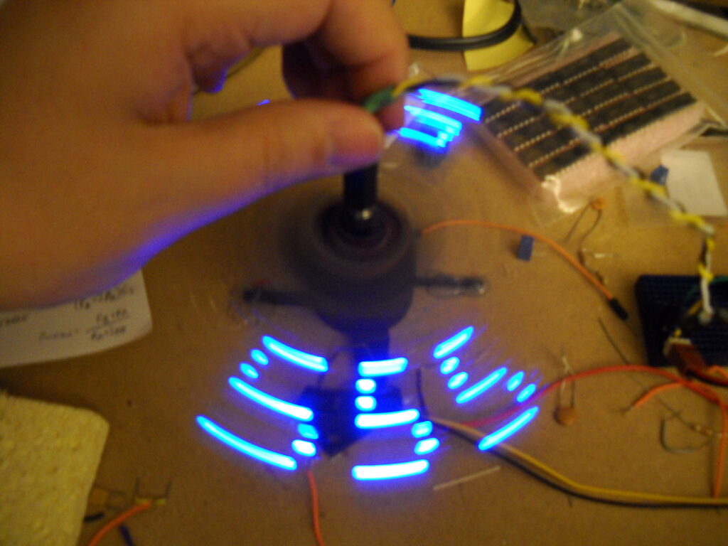
I created this display for the 555 timer contest, a compact art piece that cries out in appreciation of the venerable 555 timer. It’s a persistence of vision display formed by 7 blue leds and 3 NE555 timers, which spells out 5 5 5 as it revolves.

Theory of Operation

  • The first 555 is setup as an astable oscillator, with the reset triggered by the tachometer output of the PC fan that the whole thing is mounted on. This timer generates the ‘horizontal’ parts of the 5.
  • The second 555 is positive edge triggered (using a transistor NOT and a capacitor to generate the level input the 555 wants), and generates the *right* edge of the 5 (kind of counter-intuitive, but it spins counterclockwise).
  • The third 555 is negative edge triggered (capacitor filter) and generates the left edge of the 5.
  • Three 5’s are created by tuning the first astable 555’s period to complete 3 cycles in 1/4 of a revolution (the tachometer is high for 1/4 rev, low for 1/4, high for 1/4, low for 1/4, so you get two copies per full revolution).
Persistence of vision display using 555 timers

The original writeup for the compo is still available at http://auia.net/timercompo/pov555entry.html.

Robotender Mk. 1

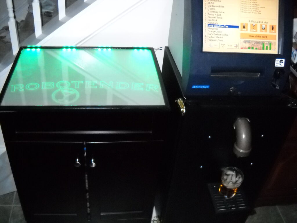
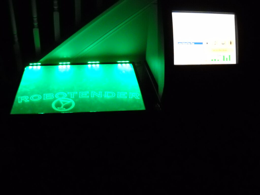
Robotender is a robotic bartender. It can mix any quantity of 9 different liquids together to make a wide range of drinks. The touch screen allows a recipe and drink size to be selected and it will then be poured. If a recipe contains any ingredients that aren’t currently loaded into a reservoir, the screen will instruct you to pour that one in manually. One of the most enjoyable drinks to pour is a Long Island Ice Tea, which causes 5 reservoirs to activate in quick succession, and only needs to be topped off with a touch of Cola for color.

The system works with a set of pressurized reservoirs and electronically controlled solenoid valves.  When a valve is activated, the pressure forces the liquid out and into the glass.

Conceived of many years ago and built in the fall of 2008.

Full system test (Dec 4th)